第8回は今までのセンサー&機器類を総動員し、旅を楽しくするArduino端末Ver1を作成します。
第7回はこちらからどうぞ
旅を楽しくするArduino端末Ver1の構成
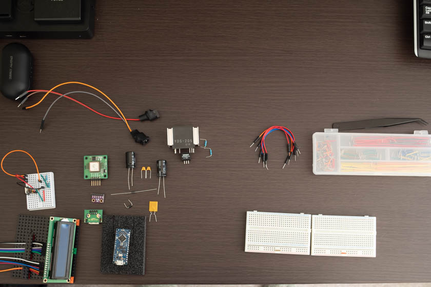
今回作成する端末は以下の構成とします。
・arduino nano every(制御用マイコン)
・LCD1602(センサー値表示用LCD)
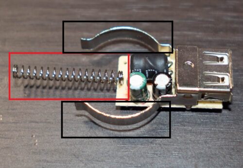
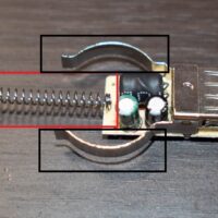
・USB2.0端子(スマートフォン充電用) + カーボン抵抗(2A給電仕様にする為)
・BME280(温度・湿度・気圧測定用)
・GPSモジュール:GYSFDMAXB(進路方角取得用)
・DC-DCコンバータ9V,0.5A(Arduino給電用)&コンデンサー&ポリスイッチ
・DC-DCコンバータ5V,2A:YDS-205(スマートフォン充電用)
・ユニバーサル基盤D基板1枚+C基板1枚(電源部と制御部用)
以上の構成で作成を行います。製作する前に回路図を書き、おおよその部品配置を検討します。
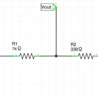
回路
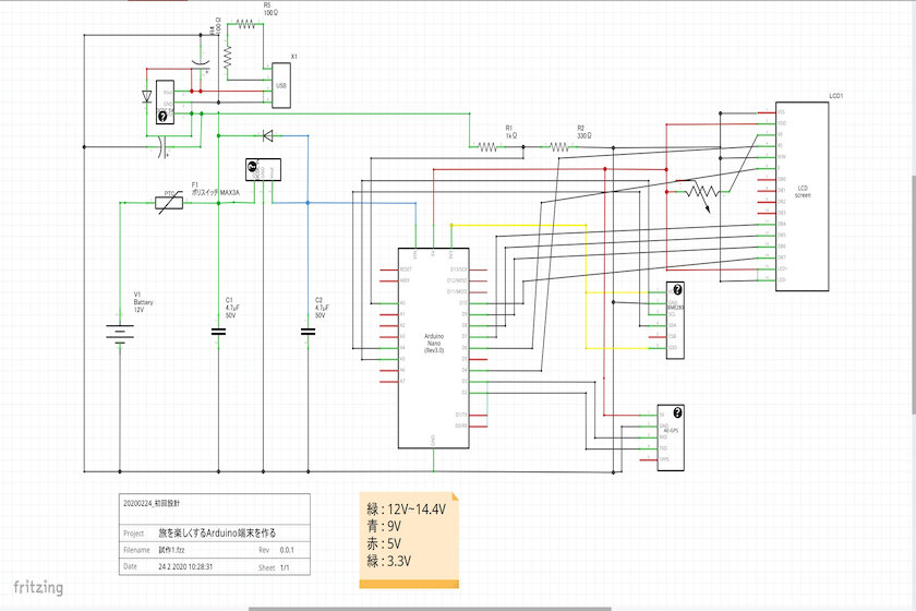
上の図が今回作成する旅を楽しくするArduino端末の回路設計図になります。
設計してから思ったのですが、9VのArduino供給用の電源は正直分離する必要はありませんでしたね。5V3A出力のDC-DCに置き換えてUSB給電部と共有させるともう少しスマートになると思います。
また、この回路で唯一3.3V駆動なのがBME280です。5Vでも動作はするのですが、推奨値ではないので、Arduinoから3.3Vを給電しています。
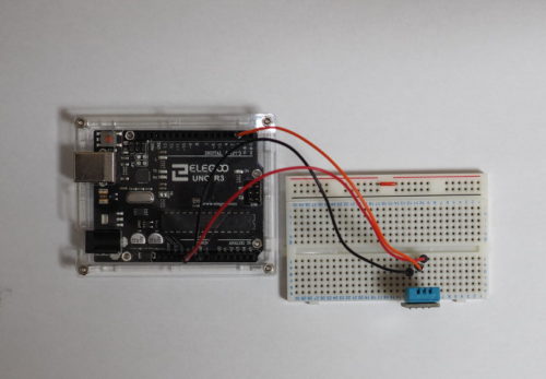
また、実物に関しては、電源部と制御部を分けた作りにしています。
バッテリーから近いシート下に、電源部をまとめ、そこから屋外配線用の4線ケーブルを用い、ハンドル部まで電源&信号を配線しています。
ちなみに4線の内訳は
① +9V
② +5V
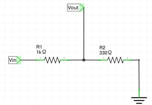
③ 0-5V(バッテリー電圧を分圧回路で降圧させた信号)
④ GND
となっております。
外装設計
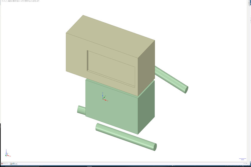
また今回はバイクへの積載を考慮しなければならないので、制御部(LCD液晶がある部分)の外装設計を行っています。
外装の素材はホームセンターで購入したアクリル板を切り出し箱状にする予定です。
設置場所はバイクのハンドル右側にある、フルードタンク上を想定しています。
3DCADで設計を行い、算出した寸法を元にアクリル板から切り出して、エポキシ系接着剤で箱状にします。
設計して気づいたのですが、意外とフルードタンク上部は他のケーブルと干渉しやすく、大きいものを設置するには向いてないですね。
コード
#include <TinyGPS++.h>
#include <SoftwareSerial.h>
#include <LiquidCrystal.h>
#include "SparkFunBME280.h"
#include "Wire.h"
#include "SPI.h"

static const int TXPin = 2, RXPin = 3;
static float m_fltCurrentTemperature;
static float m_fltCurrenthumidity;
static float m_fltCurrentPressure;
static float m_fltCurrentVoltage;
static float m_fltCurrentCourse;
static float m_fltCurrentAltitude;


TinyGPSPlus gps;
SoftwareSerial ss(TXPin, RXPin);

BME280 Sensor;
LiquidCrystal lcd( 4, 6, 10, 11, 12, 13 );

void DisplayTmp( float temperature, float humidity, float Pressure, float Voltage, String strDirection, float Altitude )
{
  String strTemperature =  String( temperature );
  int inthumidity =  humidity;
  String strhumidity = String( inthumidity );
  int intPressure = Pressure;
  String strPressure =  String( intPressure );
  String strVoltage =  String( Voltage );
  int intAltitude = Altitude;
  String strAltitude =  String( intAltitude );

  String strDisplay = "T";

  strDisplay.concat( strTemperature );
  strDisplay.concat( " H" );
  strDisplay.concat( strhumidity );
  strDisplay.concat( " P" );
  strDisplay.concat( strPressure );
  lcd.setCursor(0, 0);
  lcd.print( strDisplay );

  strDisplay = "V";
  strDisplay.concat( strVoltage );
  strDisplay.concat( " A" );
  strDisplay.concat( strAltitude );
  strDisplay.concat( " " );
  strDisplay.concat( strDirection );
  lcd.setCursor(0, 1);
  lcd.print( strDisplay );
}

String ConvertDegrees( float intCourseDegrees ){
  String strDirection;
  if ((intCourseDegrees) <= 0) {
     strDirection = "XXX";
    }
    else if ((intCourseDegrees) > 360) {
     strDirection = "XXX";
    }
    else if ((intCourseDegrees) < 11.3) {
     strDirection = "N";
     }
    else if ((intCourseDegrees) < 33.8) {
     strDirection = "NNE";
     }
   else if ((intCourseDegrees) < 56.3) {
     strDirection = "NE";
     }
   else if ((intCourseDegrees) < 78.8) {
     strDirection = "ENE";
     }
   else if ((intCourseDegrees) < 101.3) {
     strDirection = "E";
     }
  else if ((intCourseDegrees) < 123.8) {
     strDirection = "ESE";
     }
 else if ((intCourseDegrees) < 146.3) {
     strDirection = "SE";
     }
 else if ((intCourseDegrees) < 168.8) {
     strDirection = "SSE";
     }
 else if ((intCourseDegrees) < 191.3) {
     strDirection = "S";
     }
 else if ((intCourseDegrees) < 213.8) {
     strDirection = "SSW";
     }
else if ((intCourseDegrees) < 236.3) {
     strDirection = "SW";
     }
else if ((intCourseDegrees) < 258.8) {
     strDirection = "WSW";
     }
else if ((intCourseDegrees) < 281.3) {
     strDirection = "W";
      }
else if ((intCourseDegrees) < 303.8) {
     strDirection = "WNW";
     }
else if ((intCourseDegrees) < 326.3) {
     strDirection = "NW";
     }
else if ((intCourseDegrees) < 348.8) {
     strDirection = "NNW";
     }
else {
     strDirection = "N";
     }
     return strDirection;
  }

void setup() {
  Serial.begin(115200);
  lcd.begin( 16, 2);
  Serial.println("LCD SetUp Ready");
  while (!Serial);

  Sensor.settings.commInterface = I2C_MODE;
  Sensor.settings.I2CAddress = 0x77;
  Sensor.settings.runMode = 3;
  Sensor.settings.tStandby = 0;
  Sensor.settings.filter = 0;
  Sensor.settings.tempOverSample = 1 ;
  Sensor.settings.pressOverSample = 1;
  Sensor.settings.humidOverSample = 1;

  Serial.println("Starting BME280... ");
  delay(10);
  Sensor.begin();

  ss.begin(9600);
  ss.println("Connect Success");
}

void loop() {
  float temperature;
  float humidity;
  float Pressure;
  float Voltage;
  float Course;
  float Altitude;
  String strDirection;

  for (int i=0; i <= 1000; i++){
    while (ss.available() > 0){
      if (gps.encode(ss.read())){
        if (gps.location.isUpdated()){
          Serial.println(gps.course.deg());
          Serial.println(gps.altitude.meters());
          if ( gps.course.deg() != 0 ){
            m_fltCurrentCourse = gps.course.deg();
          }
          if ( gps.altitude.meters() != 0 ){
            m_fltCurrentAltitude = gps.altitude.meters();
          }
        }
      }
    }
  }

  strDirection = ConvertDegrees( m_fltCurrentCourse );

  temperature = Sensor.readTempC();
  humidity = Sensor.readFloatHumidity();
  Pressure = Sensor.readFloatPressure() / 100;
  // 1.46wotyousei
  Voltage = analogRead(A0)*0.0203;

  if( m_fltCurrentTemperature != temperature or m_fltCurrenthumidity != humidity or m_fltCurrentPressure != Pressure or m_fltCurrentVoltage != Voltage )
  {
    lcd.clear();
    //Serial.println(analogRead(A0));
    DisplayTmp( temperature, humidity, Pressure, Voltage, strDirection, m_fltCurrentAltitude );
    m_fltCurrentTemperature = temperature;
    m_fltCurrenthumidity = humidity;
    m_fltCurrentPressure = Pressure;
    m_fltCurrentVoltage = Voltage;
  }
    delay(1000);
}
電気回路と外装を設計しましたので、制御PGMの方に移ります。
特に難しいことはせず、今まで紹介したPGMとネット情報を参考に張り合わせで作成しています。
ただし、単体テストの時は発生しなかった問題として、GPSとBME280の測定間隔の違う問題があります。
同タイミングで値を取得しに行くと、運が良ければどちらの値も取得できるのですが、場合によっては片方の値しか取得できない場合があります。
これはデジタル固有の問題で、タイミング合わせが本当は必要なのですが、ここでは値がそろうまでループを回すようにして、この問題を回避しています。
厳密にリアルタイムの値を取得する必要は、今回はありませんのでこれで問題ないと思います。
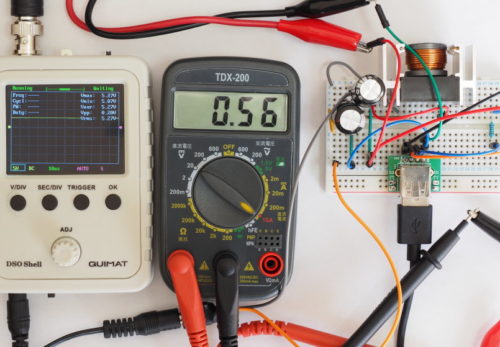
結果
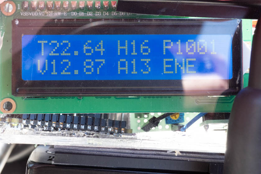
結果が1秒に1回画面が更新され、LCDに表示されます。
GPSの方も、起動時は表示されませんが、30秒以内には高度:Atitudeが表示され、走行を開始すると現在の移動方角が表示されます。
まとめ
今までこまごまと実験してきた成果が実り、端末として使えるまで作成できました。ひとまず完成です。
一番最初に挙げた不満点をすべて解消できる機能も実装でき満足しています。
ここからの改良ですが、
1.電源の5V化
2.制御部とLCD部を分離し、制御部はシート下へ
3.GPSモジュールを活用し逆Tripメーター(トリップマスター)の作成
4.LCDの有機EL化(広視野角)
を予定しています。
とりあえずはこのまま利用してみて、バグだしと改良案の実験を進めてみたいと思っています。
旅を楽しくするArduino端末を作る。リンク集
その1-不満点を挙げよう-
その2-不満点をまとめよう-
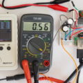
その3-電圧測定器を作る-
その4-温湿度計を作る-
その5-気圧計を作る-
その6-方位・高度計をGPSで-
その7-12Vバッテリーから電力供給
その8-Ver1作成-
その9-電圧計の誤差とその代替案-
その10-Ver2へアップデート-
その11-LCDをI2Cで制御しよう-
その12-LCDをI2C化-
その13-Ver3へアップデート-
その14-USB充電の仕様に関して-
その15-Arduino言語を用いながらBluetoothで通信できるESP32-
その16-旅Arduino Ver4 スマホアプリ化-

この記事へのコメントはありません。